Die Lines Tool Guide: Add Cut Contour Paths to PDFs for Stickers, Labels & Packaging
Learn how to add die line cut contour paths to your PDFs for die-cutting machines and flatbed cutters. Covers rectangle, ellipse, and rounded shapes, spot color naming conventions (CutContour, ThruCut, KissCut), and step-by-step setup in pdfpress.app.
What Are Die Lines (Cut Contours) and Why Do They Matter?
A die line — also called a cut contour — is a vector path embedded in a PDF that tells a cutting machine exactly where to cut, kiss-cut, score, or perforate the printed material. Unlike crop marks, which guide a guillotine trimmer along straight edges, die lines define arbitrary shapes: rounded rectangles for stickers, ellipses for circular labels, and complex outlines for custom packaging.
Die lines are not printed on the final product. They live on a dedicated spot color channel in the PDF — a separation layer that the RIP or cutter driver reads as a toolpath instruction rather than artwork. When the cutting machine processes the file, it ignores CMYK print content and follows only the spot color path, driving the blade along the contour at the configured pressure and speed.
If you produce sticker sheets, custom-shaped labels, packaging blanks, or any product that requires non-rectangular cutting, die lines are a non-negotiable part of your prepress workflow. Without them, the cutter has no instructions. With incorrect die lines — wrong spot color name, unclosed paths, misaligned contours — the cutter either refuses the job or cuts in the wrong place, wasting material and time.
The Die Lines tool in pdfpress.app adds cut contour paths directly to your PDF pages, using the same spot color naming conventions that Roland, Zünd, Summa, Mimaki, and Esko cutters expect. Everything runs locally in your browser via WebAssembly — no uploads, no server processing, and no expensive desktop software required.
Die Line Terminology: Kiss-Cut, Thru-Cut, and Spot Color Channels
Before setting up die lines, you need to understand the cutting operations they represent and the spot color names that trigger each operation. Different cutting actions require different spot color channel names, and using the wrong name means the cutter applies the wrong tool action — or ignores the path entirely.
Cutting Operations
- Thru-Cut (Through-Cut): The blade penetrates the full thickness of the substrate, completely separating the piece from the sheet. Used for packaging blanks, individual cards, hang tags, and any product that must be fully detached.
- Kiss-Cut: The blade cuts through the face material (vinyl, paper, polyester) and adhesive layer but stops at the release liner (backing). The individual sticker or label can be peeled off while the backing sheet remains intact. This is the standard operation for sticker sheets and peel-off labels.
- Crease / Score: The tool presses a fold line into the material without cutting through it. Used on packaging cartons, greeting cards, and any product that must fold cleanly along a defined line.
- Perforation: The blade creates a dashed cut — alternating cut segments and uncut bridges — allowing the user to tear the material along the line. Common for ticket stubs, reply cards, and tear-off coupons.
Spot Color Channel Names
Each cutting operation maps to a specific spot color name in the PDF. The RIP or cutter driver reads this name and routes the path to the correct tool head or pressure setting:
- CutContour — the industry-standard thru-cut channel. Recognized by Roland VersaWorks, Mimaki RasterLink, Zünd Cut Center, and most print-and-cut RIPs. This is the default and most widely compatible name.
- ThruCut — an explicit thru-cut channel used by some RIPs as an alternative to CutContour. Functionally identical but preferred by certain Esko and Kongsberg workflows.
- KissCut — triggers kiss-cut pressure. The cutter reduces blade depth to penetrate the face material only, preserving the backing liner.
- Crease — routes the path to the scoring wheel or creasing tool rather than the cutting blade.
- Perf — triggers perforation mode: the cutter alternates between cutting and skipping at intervals defined by the machine settings.
- DieCut — a generic die-cut channel. Some workflows use this as a catch-all when the specific operation is configured on the cutter rather than in the file.
Always confirm the expected spot color name with your cutter operator or RIP documentation. Using CutContour is the safest default — it is recognized by the widest range of equipment — but a Zünd operator running Esko software may expect ThruCut, and a sticker shop may need both CutContour for the outer sheet cut and KissCut for individual sticker contours on the same file.
Shape Options: Rectangle, Rounded Rectangle, and Ellipse
The Die Lines tool in pdfpress.app offers three contour shapes, covering the vast majority of die-cut products:
Rectangle
A standard rectangular die line with sharp 90° corners. This is the most common shape for business cards, shipping labels, packaging flats, and any product with straight edges. The rectangle dimensions are derived from the selected target box (TrimBox, BleedBox, or MediaBox) or entered manually when using custom dimensions.
Rounded Rectangle
A rectangle with filleted corners at a configurable radius. Rounded corners are standard for stickers, hang tags, ID badges, and loyalty cards — they resist peeling, look more polished, and are gentler on fingers and pockets. The corner radius setting controls the fillet size in PDF points:
- 8.5 pt (≈ 3 mm) — the most common radius for rounded stickers and standard hang tags
- 14 pt (≈ 5 mm) — a more pronounced rounding, typical for larger labels and ID badges
- 0 pt — sharp corners (equivalent to a plain rectangle)
When specifying radius, keep in mind that steel-rule die makers have a minimum bend radius of approximately 1.5 mm (≈ 4.25 pt). Digital cutters (Zünd, Summa) can handle tighter radii, down to about 0.5 mm, because there is no physical bending constraint on a plotter blade.
Ellipse
An elliptical (oval or circular) die line, centered on the page. Used for round stickers, coasters, drink lids, jar labels, and any circular or oval product. When the target box is square, the ellipse becomes a perfect circle. For oval shapes, use a rectangular target with unequal width and height, or enter custom dimensions.
For shapes beyond these three — freeform outlines, star bursts, custom logos — you would create the die-line path in a vector editor (Illustrator, Inkscape) and assign it a spot color before importing into pdfpress.app for prepress. The built-in shapes cover the high-frequency use cases where drawing a custom path is unnecessary overhead.
Contour Reference: TrimBox vs BleedBox vs MediaBox
Every PDF page can define multiple boundary boxes — nested rectangles that describe different aspects of the page geometry. The Die Lines tool uses these boxes as the reference boundary for the contour path. Choosing the correct target box determines where the die line sits relative to your artwork.
- TrimBox — the final finished size after trimming. This is the most common choice for die lines. Selecting TrimBox places the contour exactly at the intended cut boundary of the printed product. For a 3×2 inch sticker, the die line follows the 3×2 inch TrimBox edge.
- BleedBox — the area that includes bleed (typically 3 mm beyond the TrimBox on each side). Selecting BleedBox places the die line at the bleed boundary. This is useful when you want the cut contour to land outside the visible print area — for instance, when the die line serves as a registration-only reference that should not intersect the artwork.
- MediaBox — the full physical page size, including all marks, bleed, and slug area. Use MediaBox when the die line should encompass the entire page — uncommon for production die lines but useful for sheet-level contour cuts on digital flatbed cutters.
- Custom — enter explicit width and height in PDF points (72 pt = 1 inch = 25.4 mm). The custom contour is centered on the page by default. Use the Offset X and Offset Y fields to shift the die line from center. Custom dimensions are essential when the die-cut shape does not match any standard PDF box — for example, a small centered label on an oversized press sheet.
If your PDF does not define a TrimBox or BleedBox (common in files exported from non-prepress applications), the tool falls back to the MediaBox. To get accurate die line placement, ensure your PDF has proper page boxes set. You can verify this using the pdfpress.app Preflight panel, which reports all defined boxes for each page.
Step-by-Step: Adding Die Lines in pdfpress.app
Follow this workflow to add cut contour paths to your PDF using the Die Lines tool. The entire process runs locally in your browser — no file uploads, no plugins, no subscriptions.
- Open pdfpress.app: Navigate to pdfpress.app and load your PDF by dragging it onto the workspace or clicking the upload button. The preview pane renders your pages immediately.
- Verify page geometry: Open the Preflight / Info panel to confirm your page dimensions, TrimBox, and BleedBox are correct. If boxes are missing, use the Page Boxes tool to set them before adding die lines.
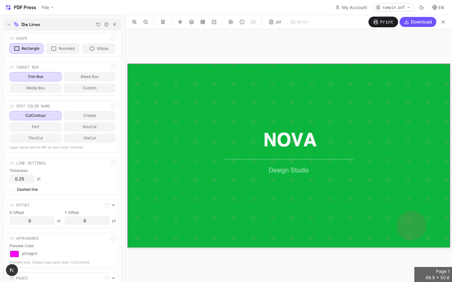
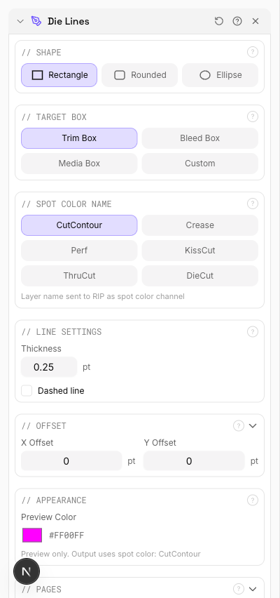
- Select the Die Lines tool: In the left sidebar, find and click Die Lines (also labeled "Cut Contour"). The options panel appears on the right.
- Choose a shape: Select Rectangle, Rounded Rectangle, or Ellipse depending on your product. For rounded stickers, choose Rounded Rectangle and set the corner radius (e.g., 8.5 pt for a 3 mm fillet).
- Select the target box: Choose TrimBox for most workflows. If your die line needs to sit at a non-standard position, select Custom and enter the width and height in points.
- Set the spot color name: Choose the spot color channel that matches your cutter's expected input. CutContour is the safe default for most Roland, Mimaki, and Zünd workflows. Select KissCut for sticker-sheet face cuts, Crease for fold lines, or Perf for perforations.
- Adjust line settings: Set the line thickness (0.25 pt is the industry standard for digital cutters). Enable dashed if you need a visual distinction for score or perf lines. Adjust offset X/Y if the die line must be shifted from the target box boundary.
- Select page range: Apply to all pages or specify a range (e.g., "1-4" or "1,3,5"). Each page receives its own contour path.
- Preview: The live preview overlays the die line on your pages in the selected preview color (magenta by default). Verify alignment, shape, and position.
- Generate: Click Generate to produce the output PDF. The die line is embedded as a spot color vector path — ready for your RIP or cutter software.
The output PDF contains the die line as a vector stroke on the specified spot color separation. When opened in a viewer like Acrobat, you can verify the spot color by checking the Output Preview panel (Print Production → Output Preview) and toggling separations. The die line should appear only on its named spot channel, not on any CMYK plate.
Spot Color Naming Conventions for Different Cutters
The spot color name in your die line is not decorative — it is a machine instruction. Different cutter manufacturers and RIP software expect specific channel names. Using the wrong name means the cutter will not recognize the path. Here is a reference for the most common equipment:
Roland VersaWorks / TrueVIS
Roland's print-and-cut ecosystem expects CutContour as the primary thru-cut channel. VersaWorks also recognizes PerfCutContour for perforation and HalfCutContour for kiss-cuts on some models. The spot color must be defined in the PDF as a named separation — VersaWorks ignores paths that are not on a recognized spot channel.
Mimaki RasterLink
Mimaki cutters follow the Roland convention: CutContour for thru-cut. RasterLink additionally supports defining multiple cut layers for multi-pass cutting on thick substrates. Each pass can be assigned to a separate spot color with sequential naming.
Zünd Cut Center / Esko Kongsberg
Zünd and Esko workflows are more flexible with spot color names but commonly use ThruCut, KissCut, Crease, and Perf. The Zünd Cut Center software allows you to map any spot color name to any tool in the multi-tool head, so you can use custom names — but sticking to the standard names avoids configuration headaches when files move between operators.
Summa
Summa flatbed and roll cutters typically read CutContour through their GoSign or Summa Cutter Control software. For multi-operation jobs, Summa supports layered spot colors where each named channel triggers a different pressure or tool setting.
General Best Practice
When in doubt, use CutContour — it is the closest thing to a universal standard. If your job requires multiple operations on a single file (e.g., thru-cut for the sheet outline and kiss-cut for individual sticker contours), use CutContour for the thru-cut and KissCut for the face cut. Confirm with your cutter operator that their RIP maps both names correctly.
Combining Die Lines with Other Tools: The Sticker Sheet Workflow
Die lines are rarely used in isolation. In a typical sticker or label production workflow, the Die Lines tool is one step in a multi-tool pipeline. Here is the standard sequence for producing a print-ready sticker sheet in pdfpress.app:
1. Design → Single Sticker PDF
Start with your individual sticker design exported as a PDF with correct page dimensions (the finished sticker size) and bleed. Ensure the TrimBox matches the sticker's finished dimensions and the artwork bleeds 2–3 mm beyond the TrimBox on all sides.
2. Die Lines → Add Kiss-Cut Contour
Use the Die Lines tool to add a KissCut contour to each sticker page. Select the TrimBox as the target, choose your shape (Rounded Rectangle with a 3 mm radius is the most common for stickers), and set the spot color to KissCut. This embeds the individual sticker cut path.
3. Grid / Step-and-Repeat → Arrange on Sheet
Use the Grid or Step & Repeat tool to arrange the sticker across the press sheet. Set rows, columns, and gutter spacing (typically 2–3 mm between stickers to allow matrix stripping). The die line contour from step 2 is duplicated with each instance, so every sticker on the sheet gets its own kiss-cut path.
4. Die Lines Again → Add Thru-Cut Outline
After prepress, add a second die line operation: this time a CutContour (thru-cut) around the entire sheet. Select the TrimBox of the imposed layout and use a Rectangle shape. This outer contour tells the cutter where to cut the sheet itself, separating it from the press sheet.
5. Cutter Marks → Registration Targets
Add Cutter Marks (registration targets) for the cutting machine's optical sensor. Place cross or circle marks outside the die-cut area. The cutter reads these marks to align the blade path with the printed artwork, compensating for any sheet-to-sheet variation.
This pipeline — design, die line, impose, die line, register — produces a fully equipped sticker sheet PDF that a print-and-cut operator can load directly into their RIP software. Every tool in the chain runs in pdfpress.app without leaving the browser.
Troubleshooting Common Die Line Issues
Even with the right tools, die line problems can surface during cutting. Here are the most frequent issues and how to resolve them:
Cutter Does Not Recognize the Die Line
Cause: The spot color name does not match what the RIP expects. Some RIPs are case-sensitive — cutcontour is not the same as CutContour.
Fix: Verify the exact channel name your RIP expects. pdfpress.app uses the standard capitalization (CutContour, KissCut, ThruCut) which matches Roland, Mimaki, and most Zünd configurations. If your RIP uses a non-standard name, some RIPs allow spot color remapping in their settings.
Die Line Is Offset from the Artwork
Cause: The target box (TrimBox, BleedBox) does not match the expected page geometry, or the PDF has incorrect box definitions.
Fix: Open the Preflight panel in pdfpress.app and verify that the TrimBox matches your intended cut boundary. If the TrimBox is missing or wrong, use the Page Boxes tool to correct it before adding die lines. Also check the Offset X/Y values — unintentional offsets shift the contour from its expected position.
Die Line Prints on the Sheet
Cause: The die line path was placed on a process color (CMYK) instead of a spot color separation, so the RIP treats it as artwork and sends it to print plates.
Fix: When using pdfpress.app, the Die Lines tool always outputs on a named spot color channel — this issue only arises with manually created die lines in design applications. Verify the spot channel in Acrobat's Output Preview: the die line should appear only under its named separation, not under Cyan, Magenta, Yellow, or Black.
Kiss-Cut Goes Too Deep / Too Shallow
Cause: This is a cutter calibration issue, not a file issue. The spot color name tells the cutter which operation to perform; the blade depth and pressure are configured on the machine.
Fix: Confirm that the RIP maps KissCut to the correct pressure profile. Run test cuts on scrap material before committing to the production run. Adjust blade depth on the cutter — the PDF die line defines the path, not the mechanical parameters.
Rounded Corners Are Not Smooth
Cause: The corner radius is too small for the cutter's mechanical resolution, or the plotter speed is too high for tight curves.
Fix: For digital cutters, a minimum radius of 2 mm (≈ 5.7 pt) produces clean curves at standard cutting speeds. Reducing cutter speed around corners improves accuracy — most RIPs have a "corner deceleration" setting. For steel-rule dies, increase the radius to at least 1.5 mm (≈ 4.25 pt) to stay within the bending limit of standard 2-point rule.
Multiple Die Lines Overlap After Prepress
Cause: Die lines were added before prepress and the gutter spacing is too narrow, causing adjacent contours to overlap.
Fix: Increase gutter spacing in the Grid or Step & Repeat tool to at least 2–3 mm between adjacent die lines. Overlapping contour paths confuse the cutter — it may cut twice along the same segment or interpret the overlap as a self-intersecting path. Alternatively, add die lines after prepress using the Custom target with explicit dimensions.
Try it yourself
PDF Press runs entirely in your browser. Upload a PDF, pick a tool, and download the result — fast and private.
Open PDF Press22 Professional Imposition Tools
Every tool runs locally in your browser — fast, private, and professional-grade.
Frequently Asked Questions
Related Articles
Ready to try professional PDF imposition?
PDF Press is a browser-based imposition tool with 22 professional tools. No installation required.
Open PDF Press