OMR Marks for Automated Print Finishing: Complete Tool Guide
Learn how to add OMR (Optical Mark Recognition) marks to PDFs for automated finishing equipment. Covers binary encoding, bar placement, dimensions, and step-by-step pdfpress.app walkthrough for folders, inserters, and trimmers.
What Are OMR Marks?
OMR marks (Optical Mark Recognition marks) are small, precisely positioned black bars printed on the edge of a press sheet that communicate instructions to automated finishing equipment. Unlike decorative marks or visual aids, OMR marks are machine-readable signals — they tell folders, inserters, trimmers, and collators exactly what to do with each sheet as it passes through the finishing line at high speed.
The principle is straightforward: an optical sensor on the finishing machine reads a sequence of bars as the sheet passes a detection point. The pattern of bars — their presence or absence at specific positions — encodes a binary number. That number maps to a program stored in the machine's controller, instructing it to fold a particular way, route the sheet to a specific pocket, or trigger a cut at the right moment.
OMR marks are standard equipment in any production environment that uses automated post-press machinery. Direct mail operations, statement processing, transactional printing, and high-volume book manufacturing all depend on them. If you work with automated finishing and use pdfpress.app for prepress, adding OMR marks is a built-in capability that integrates with your existing prepress workflow.
How Finishing Machines Use OMR Marks
Automated finishing equipment reads OMR marks through optical sensors — typically infrared or visible-light photocells mounted at fixed positions along the paper path. As a sheet enters the machine, the sensor detects the contrast between the printed black bars and the white paper background. Each bar generates a signal pulse; spaces between bars generate no pulse. The machine's controller interprets the pulse pattern as a binary instruction.
Common finishing operations controlled by OMR marks:
- Folding machines: OMR marks select between pre-programmed fold patterns. A direct mail piece might fold as a letter fold (C-fold) for one program number, a Z-fold for another, or a gate fold for a third — all on the same production run, switched automatically by the OMR code on each sheet.
- Inserters (mail enclosing machines): OMR marks on statement pages tell the inserter where a set begins and ends (collation marks), which inserts to include (selective inserts), and when to seal the envelope. A bank statement with 3 pages and a promotional insert uses different marks than one with 7 pages and no insert.
- Trimmers and cutters: OMR marks can signal a programmable cutter to apply different trim patterns — for example, trimming a finished-size A4 piece versus a DL piece from the same press run.
- Collators and gatherers: Marks identify individual sheets within a set, ensuring the correct pages are assembled in order before binding or enclosing.
The key advantage of OMR over manual program switching is inline flexibility. A single finishing run can process sheets with different programs without stopping the machine. The sensor reads each sheet's OMR code and the controller adjusts the operation in real time, often at speeds exceeding 30,000 sheets per hour.
OMR Encoding Explained: Binary Bar Patterns
OMR marks encode information using a binary system. Each bar position in the OMR sequence represents a bit. A bar present at that position equals 1; no bar equals 0. The resulting binary number maps to a finishing program.
How binary encoding works in practice:
| Program Number | Binary | Bar Pattern (● = bar, ○ = space) |
|---|---|---|
| 0 | 000 | ○ ○ ○ |
| 1 | 001 | ○ ○ ● |
| 2 | 010 | ○ ● ○ |
| 3 | 011 | ○ ● ● |
| 4 | 100 | ● ○ ○ |
| 5 | 101 | ● ○ ● |
| 6 | 110 | ● ● ○ |
| 7 | 111 | ● ● ● |
With 3 bar positions, you can encode 8 programs (2³ = 8). With 5 positions, you get 32 programs. Most production environments use between 3 and 8 bar positions, providing 8 to 256 possible programs — more than sufficient for even complex finishing configurations.
Additional control marks: Beyond the program number, OMR sequences often include special-purpose marks:
- Start mark (timing mark): A fixed bar that synchronizes the sensor with the sheet. Always present, always at the same position — the sensor uses it to know "reading starts here."
- Sequence mark: Indicates whether the current sheet is the first, middle, or last page in a multi-sheet set (critical for inserters).
- Parity mark: An error-detection bit that verifies the integrity of the read. If the parity doesn't match, the machine stops or rejects the sheet.
- Selective marks: Additional bits that trigger or suppress specific actions (e.g., "include insert A," "skip insert B").
The exact encoding scheme varies by equipment manufacturer. Pitney Bowes, Bowe Bell + Howell, Kern, and Hunkeler each define their own mark specifications. pdfpress.app lets you configure the number of bar positions and their values to match your specific machine's requirements.
OMR Bar Dimensions and Specifications
OMR bars must meet precise dimensional requirements for reliable sensor detection. While specifications vary by manufacturer, industry-standard dimensions are well established.
Typical bar dimensions:
- Bar width: 0.4mm to 0.6mm (0.016" to 0.024"). Wider bars are more reliably detected but consume more edge space.
- Bar height (length): 4mm to 12mm (0.16" to 0.47"). The bar must be tall enough for the sensor's field of view. Taller bars provide more tolerance for sheet skew during feeding.
- Bar spacing (pitch): 2.54mm (0.1") center-to-center is the most common pitch, matching the resolution of standard OMR sensors. Some systems use 5.08mm (0.2") pitch for coarser detection.
- Start mark offset: The distance from the leading edge of the sheet to the first bar, typically 6mm to 25mm depending on the machine's feed mechanism and sensor position.
Ink requirements: Bars must be printed in solid black (100% K) on white or near-white paper. The contrast ratio between bar and background must exceed 60% for reliable detection. Colored or tinted papers may require special sensor calibration. Never print OMR bars in process color builds (CMY) — the infrared sensors used by many machines cannot detect cyan or yellow ink reliably.
Print quality: Bars must have clean, sharp edges. Feathering, bleeding, or toner spatter near the bars can cause misreads. Laser and high-resolution inkjet output works well; low-resolution inkjet or offset on uncoated stock may require testing.
OMR Mark Placement: Edge Selection and Orientation
OMR marks are placed along one edge of the sheet, perpendicular to the direction of travel through the finishing machine. The choice of edge depends on how the machine feeds paper and where its sensors are positioned.
Edge options:
- Top edge: The most common placement for inserters and mail-processing equipment. The sheet feeds long-edge first, and the sensor reads marks along the top (leading) edge as the sheet enters the machine.
- Bottom edge: Used when the finishing machine feeds from the opposite direction or when the top edge carries other marks (e.g., address block, barcodes).
- Left edge: Common for folding machines where the sheet feeds short-edge first. Marks run vertically along the left side of the sheet.
- Right edge: The mirror of left-edge placement, used for machines with right-side sensors or when the sheet is fed right-edge leading.
Distance from edge: Bars should sit 3mm to 8mm from the physical edge of the sheet. Too close to the edge risks the bars being cut off by imprecise trimming or missed by the sensor due to sheet curl. Too far from the edge and the sensor may not reach them.
Relationship to other marks: OMR bars must not overlap with crop marks, registration marks, or color bars. Allocate dedicated zones along the sheet edge for each mark type. A common layout reserves the first 30mm of the leading edge for OMR, followed by crop marks, then registration marks further along the edge.
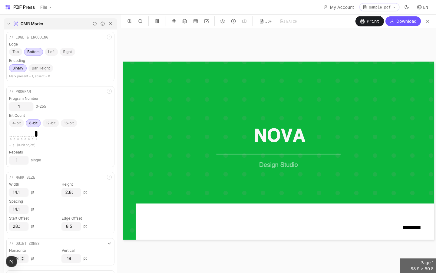
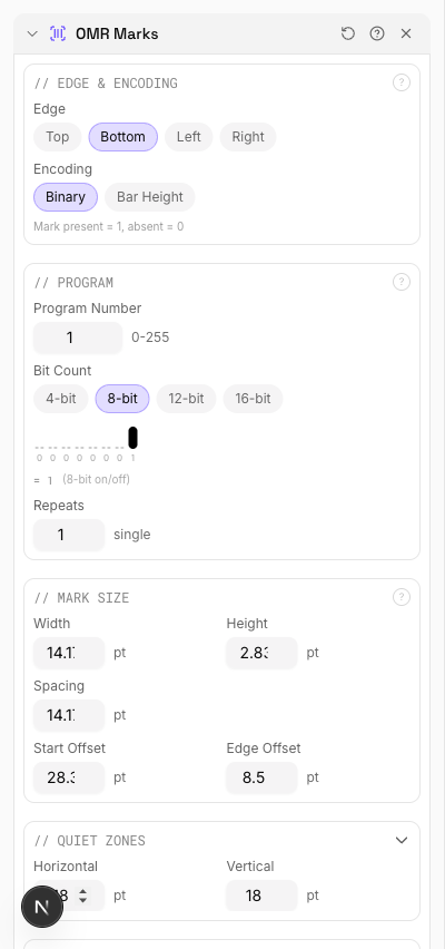
Adding OMR Marks with pdfpress.app: Step-by-Step
pdfpress.app includes a dedicated OMR Marks tool that generates correctly dimensioned, properly positioned bars for any finishing equipment. The entire process runs in your browser — no files leave your computer.
Step-by-step walkthrough:
- Upload your PDF to pdfpress.app. The file loads instantly in the browser-based preview, showing page dimensions and any existing marks.
- Add the OMR Marks tool from the toolbox. It appears as a pipeline step that you can position before or after other mark tools in your workflow.
- Select the edge: Choose top, bottom, left, or right to match your finishing machine's sensor position.
- Set the program number: Enter the finishing program number. pdfpress.app automatically converts it to the correct binary bar pattern and displays the resulting sequence.
- Configure bar dimensions: Set bar width, height, pitch, and edge offset to match your equipment specifications. Default values follow industry standards and work with most machines.
- Add control marks: Enable or disable the timing mark, sequence mark, and parity mark as required by your finishing equipment.
- Preview the result. The real-time preview shows the exact bar positions on the sheet. Zoom in to verify spacing and alignment.
- Download the finished PDF. OMR bars are rendered as vector elements at the correct dimensions, producing sharp, sensor-readable marks at any print resolution.

Pipeline integration: OMR marks work alongside other pdfpress.app tools. A typical direct mail workflow chains Prepress (page layout) → OMR Marks (finishing instructions) → Crop Marks (trim guides) → Barcode (tracking). Each tool adds its layer, and the preview updates after every change.
Integrating OMR Marks with Other Production Marks
A production press sheet carries multiple mark systems simultaneously, each serving a different purpose. OMR marks must coexist with all of them without interference.
Mark coexistence strategy:
- OMR + Crop marks: OMR bars occupy a dedicated zone along one edge. Crop marks sit at the corners of the trim area. No conflict as long as the OMR zone doesn't extend into corner mark territory.
- OMR + Gathering marks: Gathering marks go on the spine fold edge for signature collation. OMR marks go on the leading edge for finishing instructions. Different edges, no overlap.
- OMR + Lay marks: Lay marks indicate gripper edge and side guide orientation. They occupy small zones at the gripper and guide edges. If OMR marks share the gripper edge, position them with sufficient clearance from lay marks (minimum 10mm separation).
- OMR + Color bars: Color control strips typically run along the trailing edge or across the full width in the slug area. OMR marks on the leading edge will not conflict.
- OMR + Barcodes: Some workflows use both OMR marks for finishing instructions and barcodes for tracking or addressing. Ensure they occupy different zones — OMR along one edge, barcode in the address block or a separate edge zone.
pdfpress.app's pipeline approach makes multi-mark layouts manageable. Add each mark type as a separate tool step, preview the composite result, and adjust positions if any marks overlap.
Troubleshooting OMR Mark Problems
When finishing machines misread OMR marks, production stops. Here are the most common issues and their solutions.
1. Machine fails to detect any marks.
- Cause: Bars printed too faintly (low toner density) or in a color the sensor cannot detect (cyan, yellow, or a CMYK build instead of 100% K).
- Fix: Print OMR bars in 100% black only. Verify toner/ink density on a test sheet with a densitometer — target a minimum density of 1.2 D.
2. Intermittent misreads.
- Cause: Bar dimensions outside the sensor's detection window, or bar pitch doesn't match the sensor's expected spacing.
- Fix: Confirm bar width, height, and pitch against the machine manufacturer's specification sheet. Even 0.1mm deviations in pitch can cause misreads at high speed.
3. Incorrect program executed.
- Cause: Binary encoding order (MSB vs LSB first) doesn't match the machine's expected bit order.
- Fix: Verify whether your machine reads most-significant-bit first or least-significant-bit first. Reverse the bar order if needed.
4. Marks detected on wrong edge.
- Cause: Sheet fed into the machine with incorrect orientation — the edge carrying OMR marks isn't passing the sensor.
- Fix: Add lay marks to indicate correct sheet orientation. Train operators to verify feeding direction before starting the run.
5. Marks clipped by trimming.
- Cause: OMR bars positioned too close to the trim edge, partially or fully removed during upstream cutting.
- Fix: Move bars at least 5mm from any trim line. Verify the sheet arrives at the finishing machine before final trimming, not after.
Testing protocol: Always run a small test batch (10-20 sheets) through the finishing machine before committing to a full production run. Verify that every program number triggers the correct operation, that sequence marks correctly identify first/last sheets in a set, and that the machine rejects sheets with deliberately corrupted marks.
Try it yourself
PDF Press runs entirely in your browser. Upload a PDF, pick a tool, and download the result — fast and private.
Open PDF Press22 Professional Imposition Tools
Every tool runs locally in your browser — fast, private, and professional-grade.
Frequently Asked Questions
Related Articles
Ready to try professional PDF imposition?
PDF Press is a browser-based imposition tool with 22 professional tools. No installation required.
Open PDF Press